The Climb Assist System - Wind Turbine Application
The Climb Assist System
Wind Turbine Application
October 2022
Key aspects: Concept Generation, CAD Design, FEA Analysis (compared to Analytical results), Serviceability Analysis, Fit Tolerances, Sourced Components Selections, Safety measures, Mass optimization (add-in), Costing (add-in), Bill-of-Materials and Engineering Report.
Group Size: 3 people
Group Size: 3 people
Project duartion: 10 weeks
Project duartion: 10 weeks
Course Name: Machine Desing
Course Name: Machine Desing
Key aspects: Concept Generation, CAD Design, FEA Analysis (compared to Analytical results), Serviceability Analysis, Fit Tolerances, Sourced Components Selections, Safety measures Implemented, Mass optimization (add-in), Costing (add-in), Bill-of-Materials and Engineering Report.
Group Size: 3 people
Project duartion: 10 weeks
Course Name: Machine Design
Objective:
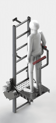
To design a Climb Assist System that facilitates the process of transporting passengers and material from the base to nacelle of a wind turbine. The design of the lift had to follow a very thorough engineering analysis.
Requirements:
Rack and pinion mechanism needed to be used to climb up.
System assembled/disassembled with ease.
The Climb assist system was designed to carry a 100 kg person plus 20 kg of extra cargo while being able to climb 120 meters in 2.5 minutes.
Design details.
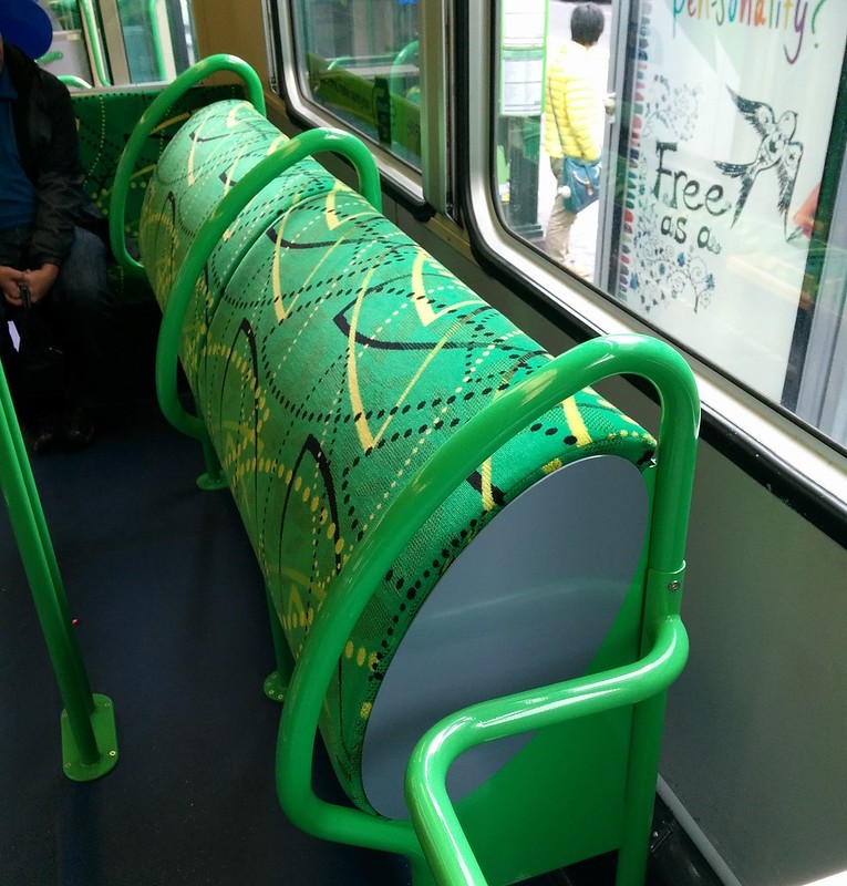
After multiple concepts, we arrived to the the final design, consisting of two main linkages, a single arm rest and stand-up seat.
Stand up Seat inspired from the Melbourne tram design.
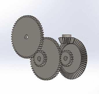
Fully working 90-degree 3 stage gearbox with casing designed.
Off the shelf components selected such as motor and controller.
Engineering drawings for manufacturing.
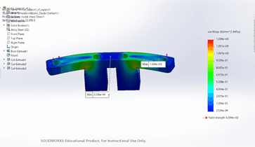
Engineering Analysis
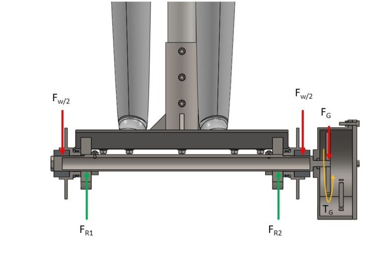
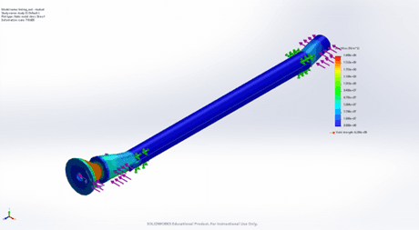
FEA and hand calculations performed on 8 major components, under a safety factor of 3.
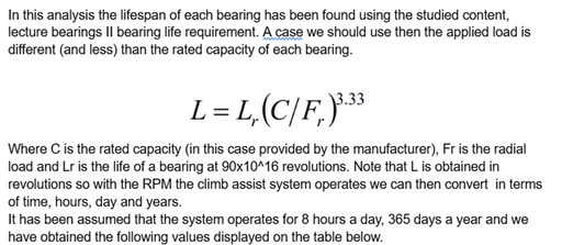
Fatigue Analysis for serviceability of lift performed on the main shaft and bearings.
Tolerancing for fits: Bearings, shafts, and bearings housing.
Optimization for mass weight and cost (maintaining safety factor).
SolidWorks Costing and Optimization tools.
Other aspects included:
Full costing report and BOM.
Safety measures, failure analysis and forms of mitigation.
Report with the design process to present to the hypothetical client.
My contribution in the design process was selecting the motor and designing the gearbox and its attachments to the main linkage.
I also performed the majority of the FEA analysis and modified the needed parts to meet the FoS.
Lastly, I drove the calculations for the bearings serviceability and contributed to the final report that encompassed the design process of this machine.
Disclaimer: The scope of the project was limited to research, design, analysis and drawings. The lift was not brought to life. :(
Requirements:
Rack and pinion mechanism needed to be used to climb up.
System assembled/disassembled with ease.
The Climb assist system was designed to carry a 100 kg person plus 20 kg of extra cargo while being able to climb 120 meters in 2.5 minutes.
Design details.
After multiple concepts, we arrived to the the final design, consisting of two main linkages, a single arm rest and stand-up seat.
Stand up Seat inspired from the Melbourne tram design.
Fully working 90-degree 3 stage gearbox with casing designed.
Off the shelf components selected such as motor and controller.
Engineering drawings for manufacturing.
Engineering Analysis
FEA and hand calculations performed on 8 major components, under a safety factor of 3.
Fatigue Analysis for serviceability of lift performed on the main shaft and bearings.
Tolerancing for fits: Bearings, shafts, and bearings housing.
Optimization for mass weight and cost (maintaining safety factor).
SolidWorks Costing and Optimization tools.
Other aspects included:
Full costing report and BOM.
Safety measures, failure analysis and forms of mitigation.
Report with the design process to present to the hypothetical client.
My contribution in the design process was selecting the motor and designing the gearbox and its attachments to the main linkage.
I also performed the majority of the FEA analysis and modified the needed parts to meet the FoS.
Lastly, I drove the calculations for the bearings serviceability and contributed to the final report that encompassed the design process of this machine.
Disclaimer: The scope of the project was limited to research, design, analysis and drawings. The lift was not brought to life.